


A Pocket PC can connect to the Internet via a wired modem in one of two ways. If the Pocket PC has a Bluetooth Internet connection, it can connect to a wired modem that has Bluetooth technology or a Bluetooth modem connected to it. If the Pocket PC has WiFi capabilities, it can connect to any wired modem that has a wireless router connected to it.
Connecting to a Wired Modem with Bluetooth
Pocket PCs with Bluetooth capability must first have the Bluetooth connection enabled. If the modem has Bluetooth built in, this should also be enabled. If the modem lacks Bluetooth, a seperate Bluetooth router can be purchased and connected via ethernet cable to broadband modems or directly to a dial-up modem with a standard phone line.If a modem has Bluetooth or a Bluetooth router connected but the Pocket PC lacks Bluetooth, a Bluetooth CompactFlash Type 2 adapter card can be purchased, giving the Pocket PC instant Bluetooth connectivity. The Pocket PC will discover the Bluetooth modem connection and connect to it.
Connecting to a Wired Modem with WiFi
This common way of connecting WiFi devices to a wired modem requires that a wireless router be connected to the wired modem. This wireless router connects to the modem via ethernet cable. The Internet connection is then made available to nearby wireless devices through a signal transmitted by the wireless router. Enabling WiFi on a Pocket PC with WiFi capabilities will allow the device to detect the wireless Internet connection and connect to it.Wireless routers may be encrypted and require a user name and password to access the secure wireless connection. When WiFi is enabled on a Pocket PC or PDA device, the device will scan for nearby networks and display both secured and unsecured networks. If the user lacks access to a secure network, the device can connect to public or unsecured wireless networks if they are available
Friday, March 26, 2010
Sunday, February 14, 2010
HTTP Message Structure


Like most network protocols, HTTP uses the client-server model: An HTTP client opens a connection and sends a request message to an HTTP server; the server then returns a response message, usually containing the resource that was requested. After delivering the response, the server closes the connection. The format of the request and response messages are similar and will have following structure:
Initial lines and headers should end in CRLF. Though you should gracefully handle lines ending in just LF. More exactly, CR and LF here mean ASCII values 13 and 10. Initial Line : RequestThe initial line is different for the request than for the response. A request line has three parts, separated by spaces:
Here is an exampple of initial line for Request Message.
Initial Line : ResponseThe initial response line, called the status line, also has three parts separated by spaces:
Here is an exampple of initial line for Response Message.
Header LinesHeader lines provide information about the request or response, or about the object sent in the message body. The header lines are in the usual text header format, which is: one line per header, of the form "Header-Name: value", ending with CRLF. It's the same format used for email and news postings, defined in RFC 822.
Here is an exampple of ione header line
The Message BodyAn HTTP message may have a body of data sent after the header lines. In a response, this is where the requested resource is returned to the client (the most common use of the message body), or perhaps explanatory text if there's an error. In a request, this is where user-entered data or uploaded files are sent to the server. If an HTTP message includes a body, there are usually header lines in the message that describe the body. In particular:
|
message body
HTTP Message Structure
Like most network protocols, HTTP uses the client-server model: An HTTP client opens a connection and sends a request message to an HTTP server; the server then returns a response message, usually containing the resource that was requested. After delivering the response, the server closes the connection. The format of the request and response messages are similar and will have following structure:
Initial lines and headers should end in CRLF. Though you should gracefully handle lines ending in just LF. More exactly, CR and LF here mean ASCII values 13 and 10. Initial Line : RequestThe initial line is different for the request than for the response. A request line has three parts, separated by spaces:
Here is an exampple of initial line for Request Message.
Initial Line : ResponseThe initial response line, called the status line, also has three parts separated by spaces:
Here is an exampple of initial line for Response Message.
Header LinesHeader lines provide information about the request or response, or about the object sent in the message body. The header lines are in the usual text header format, which is: one line per header, of the form "Header-Name: value", ending with CRLF. It's the same format used for email and news postings, defined in RFC 822.
Here is an exampple of ione header line
The Message BodyAn HTTP message may have a body of data sent after the header lines. In a response, this is where the requested resource is returned to the client (the most common use of the message body), or perhaps explanatory text if there's an error. In a request, this is where user-entered data or uploaded files are sent to the server. If an HTTP message includes a body, there are usually header lines in the message that describe the body. In particular:
|
ftp protocols link
http://www.windowsnetworking.com/articles_tutorials/Understanding-FTP-Protocol.html


 http protocols


 http protocols
HTTP Overview
HTTP stands for Hypertext Transfer Protocol. It is an TCP/IP based communication protocol which is used to deliver virtually all files and other data, collectively called resources, on the World Wide Web. These resources could be HTML files, image files, query results, or anything else. A browser is works as an HTTP client because it sends requests to an HTTP server which is called Web server. The Web Server then sends responses back to the client. The standard and default port for HTTP servers to listen on is 80 but it can be changed to any other port like 8080 etc. There are three important things about HTTP of which you should be aware:
Following diagram shows where HTTP Protocol fits in communication:  |
Saturday, February 6, 2010
Mesh Topoloy
Mesh Topoloy
In this topology, every node has a dedicated point-to-point connection to every other node on the network. A fully connected mesh network has n(n-1)/2 channels to link 'n' devices. Therefore, every device on the network must have 'n-1' input/output (I/O) ports.
In mesh network, each node is directly connected to all nodes on the network. This type of network involves the concept of routes. In this type of network, each node may send message to destination through multiple paths. It means that each node of mesh network has several possible paths to send (or to receive) message, but in Bus, Star, Ring and Tree topologies each node has only one path.

Advantages
Mesh topology has the following advantages:
- It has multiple links, so if one route is blocked then other routes can be used for data communication.
- Each connection can have its own data load, so the traffic problem is eliminated.
- It ensures the data privacy or security, because every message travels along a dedicated link.
- Troubleshooting of this topology is easy as compared to other networks.
- Its performance is not affected with heavy load of data transmission.
Disadvantages
Mesh topology has the following disadvantages:
- It becomes very expensive because a large number of cabling and 110 ports are required.
- It is difficult to install.
Tree Topology
Tree Topology
In tree network, the nodes are connected to each other in such a way that forms a tree like structure. Typically to form a tree network, multiple star topologies are combined together. This type of network has combined features of bus and star topology.
On tree topology the hubs of each star topology are connected to the central hub that controls the entire network. However, some nodes can be directly connected to the central hub. The tree topology configuration is shown in figure below.
The central Hub in the tree network is an active hub. It contains a repeater (a hardware device), which re-generates the received bit patterns. The secondary hubs usually are passive hubs. The passive hub controls the nodes directly connected to it and exchange data to other devices connected to the other secondary hubs (or same hub) through the central hub. The secondary hub may also be active hub if another secondary hub is directly connected to it. The cable TV network is an example of tree topology, where main cable is divided into, branches and each branch is further divided into smaller branches and so on. The hub is used when a branch is created.

Advantages
The tree topology has the same advantages as star topology but it has some additional advantages. These are.
- It allows more devices to be connected to the central Hub.
Disadvantages
The tree topology also has the same disadvantages as star topology built has some additional disadvantages such as:
- It because more expansive because more hubs are required to install the network.
Hybrid Topology
A ring topology is a network topology or circuit arrangement in which each network device is attached along the same signal path to two other devices, forming a path in the shape of a ring. Each device in the network that is also referred to as node handles every message that flows through the ring. Each node in the ring has a unique address. Since in a ring topology there is only one pathway between any two nodes, ring networks are generally disrupted by the failure of a single link.
The redundant topologies are used to eliminate network downtime caused by a single point of failure. All networks need redundancy for enhanced reliability. Network reliability is achieved through reliable equipment and network designs that are tolerant to failures and faults. The FDDI networks overcome the disruption in the network by sending data on a clockwise and a counterclockwise ring. In case there is a break in data flow,the data is wrapped back onto the complementary ring before it reaches the end of the cable thereby maintaining a path to every node within the complementary ring.
The most well known example of a ring topology is Token Ring.
[edit]Advantages
- An orderly network where every device has access to the token and the opportunity to transmit
- Under heavy network load performs better than a start topology.
- To manage the connectivity between the computers it doesnt need network server.
[edit]Disadvantages
- One malfunctioning workstation can throw away the entire network.
- Moves, adds and changes of devices can affect the entire network .
- It is slower than an Ethernet network.
- Although 16Mbps is the standard ring speed these days (and Fast Token Ring is being developed) we will consider a 4Mbps Token Ring in this tutorial to explain the basic concepts.

Hit 'Refresh' on your browser to start the animation from the beginning
At the start, a free Token is circulating on the ring, this is a data frame which to all intents and purposes is an empty vessel for transporting data. To use the network, a machine first has to capture the free Token and replace the data with its own message.In the example above, machine 1 wants to send some data to machine 4, so it first has to capture the free Token. It then writes its data and the recipient's address onto the Token (represented by the yellow flashing screen).
The packet of data is then sent to machine 2 who reads the address, realizes it is not its own, so passes it on to machine 3. Machine 3 does the same and passes the Token on to machine 4.
This time it is the correct address and so number 4 reads the message (represented by the yellow flashing screen). It cannot, however, release a free Token on to the ring, it must first send the message back to number 1 with an acknowledgement to say that it has received the data (represented by the purple flashing screen).
The receipt is then sent to machine 5 who checks the address, realizes that it is not its own and so forwards it on to the next machine in the ring, number 6.
Machine 6 does the same and forwards the data to number 1, who sent the original message.
Machine 1 recognizes the address, reads the acknowledgement from number 4 (represented by the purple flashing screen) and then releases the free Token back on to the ring ready for the next machine to use.
That's the basics of Token Ring and it shows how data is sent, received and acknowledged, but Token Ring also has a built in management and recovery system which makes it very fault tolerant. Below is a brief outline of Token Ring's self maintenance system.
Token Ring Self Maintenance
When a Token Ring network starts up, the machines all take part in a negotiation to decide who will control the ring, or become the 'Active Monitor' to give it its proper title. This is won by the machine with the highest MAC address who is participating in the contention procedure, and all other machines become 'Standby Monitors'.The job of the Active Monitor is to make sure that none of the machines are causing problems on the network, and to re-establish the ring after a break or an error has occurred. The Active Monitor performs Ring Polling every seven seconds and ring purges when there appears to be a problem. The ring polling allows all machines on the network to find out who is participating in the ring and to learn the address of their Nearest Active Upstream Neighbour (NAUN). Ring purges reset the ring after an interruption or loss of data is reported.
Each machine knows the address of its Nearest Active Upstream Neighbour. This is an important function in a Token Ring as it updates the information required to re-establish itself when machines enter or leave the ring.
When a machine enters the ring it performs a lobe test to verify that its own connection is working properly, if it passes, it sends a voltage to the hub which operates a relay to insert it into the ring.
If a problem occurs anywhere on the ring, the machine that is immediately after the fault will cease to receive signals. If this situation continues for a short period of time it initiates a recovery procedure which assumes that its NAUN is at fault, the outcome of this procedure either removes its neighbour from the ring or it removes itself.
Token Ring Operation using a Hub

A Token Ring hub simply changes the topology from a physical ring to a star wired ring. The Token still circulates around the network and is still controlled in the same manner, however, using a hub or a switch greatly improves reliability because the hub can automatically bypass any ports that are disconnected or have a cabling fault.
Further advancements have been made in recent years with regard to Token Ring technology, such as early Token release and Token Ring switching but as this site is primarily concerned with cabling issues we will not go into any more detail here.
BUS topology
http://ucan.us/doyetech/images/bustop.jpg
BUS TOPOLOGY
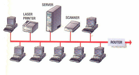
A bus network uses a multi-drop transmission medium, all node on the network share a common bus and thus share communication. This allows only one device to transmit at a time. A distributed access protocol determines which station is to transmit. Data frames contain source and destination addresses, where each station monitors the bus and copies frames addressed to itself.

( a typical bus topology)
A bus topology connects each computer (nodes) to a single segment trunk (a communication line, typically coax cable, that is referred to as the 'bus'. The signal travels from one end of the bus to the other. A terminator is required at each to absorb the signal so as it does not reflect back across the bus. A media access method called CSMA/MA is used to handle the collision that occur when two signals placed on the wire at the same time. The bus topology is passive. In other words, the computers on the bus simply 'listen' for a signal; they are not responsible for moving the signal along.
Advantages: Failure of one of the station does not affect others.
Good compromise over the other two topologies as it allows relatively high rate of data tansmittion.
Well suited for temporary networks that must be set up in a hurry.
Easy to implement and extend.
Disadvantage: Require a network to detect when two nodes are transmitting at the same time.
Does not cope well with heavy traffic rates
Difficult to administer/troubleshoot.
Limited cable length and number of stations.
A cable brake can disable the entire network; no redundancy.
Maintenance cost may be higher in the long run.
Performance degrade as additional computers are added.
stra topologi
Star network
From Wikipedia, the free encyclopedia

Star networks are one of the most common computer network topologies. In its simplest form, a star network consists of one central switch, hub or computer, which acts as a conduit to transmit messages.[1]Thus, the hub and leaf nodes, and the transmission lines between them, form a graph with the topology of astar. If the central node is passive, the originating node must be able to tolerate the reception of an echo of its own transmission, delayed by the two-way transmission time (i.e. to and from the central node) plus any delay generated in the central node. An active star network has an active central node that usually has the means to prevent echo-related problems.
The star topology reduces the chance of network failure by connecting all of the systems to a central node. When applied to a bus-based network, this central hub rebroadcasts all transmissions received from any peripheral node to all peripheral nodes on the network, sometimes including the originating node. All peripheral nodes may thus communicate with all others by transmitting to, and receiving from, the central node only. The failure of a transmission line linking any peripheral node to the central node will result in the isolation of that peripheral node from all others, but the rest of the systems will be unaffected. [2]
Contents[hide] |
[edit]Advantages
- Better performance: The star topology prevents the passing of data packets through an excessive number of nodes. At most, 3 devices and 2 links are involved in any communication between any two devices. Although this topology places a huge overhead on the central hub, with adequate capacity, the hub can handle very high utilization by one device without affecting others.
- Isolation of devices: Each device is inherently isolated by the link that connects it to the hub. This makes the isolation of individual devices straightforward and amounts to disconnecting each device from the others. This isolation also prevents any non-centralized failure from affecting the network.
- Benefits from centralization: As the central hub is the bottleneck, increasing its capacity, or connecting additional devices to it, increases the size of the network very easily. Centralization also allows the inspection of traffic through the network. This facilitates analysis of the traffic and detection of suspicious behavior.
- Simplicity: This topology is easy to understand, establish, and navigate. Its simplicity obviates the need for complex routing or message passing protocols. Also, as noted earlier, the isolation and centralization it allows simplify fault detection, as each link or device can be probed individually.
[edit]Disadvantages
The primary disadvantage of a star topology is the high dependence of the system on the functioning of the central hub. While the failure of an individual link only results in the isolation of a single node, the failure of the central hub renders the network inoperable, immediately isolating all nodes. The performance and scalability of the network also depend on the capabilities of the hub. Network size is limited by the number of connections that can be made to the hub, and performance for the entire network is capped by its throughput. While in theory traffic between the hub and a node is isolated from other nodes on the network, other nodes may see a performance drop if traffic to another node occupies a significant portion of the central node's processing capability or throughput. Furthermore, wiring up of the system can be very complex.
toplogies n thier types
What is Topology?
A topology is configuration of communication networksand is of two types, Physical and Logical. Physicaltopology refers to configuration of computers, cables, devices and mostly depends on various factors. A logical topology is a method of transmitting or passing data between workstations.
Types of Physical Topologies
- Bus Network (also known as Liner Bus)
- Star Topology (Centralization)
- Ring Topology (also known as Star-Wired or Token Ring Network)
- Tree
- Mesh Topology
Bus Network
A bus network is a network architecture in which a set of clients are connected via a shared communications line, called a bus. There are several common instances of the bus architecture, including one in the motherboard of most computers, and those in some versions of Ethernet networks.
Star Topology
In a Star Topology each computer is directly connected to the centralized Hub or a Switch. In this way, when computer A sends a data packet for computer B, the data flows through the Hub or Switch to which both computer A and B are connected. Different types of cables can be used in this scenario like coaxial cable, fibre optic cable and twisted pair cable.
Token Ring / Star-Wired
A token ring topology is architecturally similar to star topology. The only difference here is that it is created of wiring that would allow transfer of data from one computer to another in a ring (or circle). A token ring network will pass information based on token system.
Tree
A tree topology combines characteristics of linear bus and star topologies. It consists of groups of star-configured workstations connected to a linear bus backbone cable. Tree topologies allow for the expansion of an existing network with ease.
Mesh Topology
A fully connected or complete topology is a network topology in which there is a direct link between all pairs of nodes. In a fully connected network with n nodes, there are n(n-1)/2direct links. Synonym fully connected mesh network.
In a mesh topology, there are at least two nodes with two or more paths between them. A special kind of mesh, limiting the number of hops between two nodes, is a hypercube. The number of arbitrary forks in mesh networks makes them more difficult to design and implement, but their decentralized nature makes them very useful. This is similar in some ways to a grid network, where a linear or ring topology is used to connect systems in multiple directions. A multi-dimensional ring has a toroidal (torus) topology, for instance.
Considerations
Consider the following when choosing a topology:-
- Future Growth: Is the network for temporary use or will undergo lot of growth in the future. Plan it accordingly.
- Money: What is your budget? What will be the purpose of this network?
- Cable Media: Type of cable that should be used as per the standards.
- Length of the cable: How far are your systems placed in the network? Is it the same building that your systems will be placed in or if your office is in two floors which should be connected?
Summary
See the below table for a quick understanding and comparison of topologies, cable media and protocols used.
| Topology | Cable Media | Protocols Used |
|---|---|---|
| Linear Bus | Twisted Pair Coaxial Fiber | Ethernet LocalTalk |
| Star | Twisted Pair Fiber | Ethernet LocalTalk |
| Token / Star-Wired Ring | Twisted Pair | Token Ring |
| Tree | Twisted Pair Coaxial Fiber | Ethernet |
Subscribe to:
Posts (Atom)